Design A Combinational Circuit With Four Inputs

4 Bit Parallel Subtractor Parallel Logic Design

Combinational Logic Logic Electronic Engineering Circuit

2 Bit Comparator 2 Bits Logic Digital Circuit

4 Bit Comparator Logic Electronics Circuit Bits

Logic And Gate Tutorial Truth Table Electronics Area Logic Tutorial Truth

2 Bit Synchronous Up Counter Electronics Circuit Circuit Digital

The circuit must output o when the inputs are 1010 1111 and a 1 for all other.
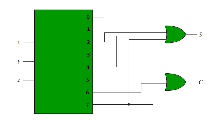
Design a combinational circuit with four inputs. 4 5 design a combinational circuit with three inputs x y and z and three outputs a b and c. Design a combinational circuit with 4 inputs and one output. The inputs are d3 do and the output goes to the blanking input of the 7447. We re going to elaborate few important combinational circuits as follows.
Solution for design a combinational circuit with 4 inputs a3 a2 a1 a0. Design a combinational circuit that will take 4 bits in binary as input and switch the first and last digits. Half adder is a combinational logic circuit with two inputs and two outputs. Even though cad tools are used to create combinational logic circuits in practice it is important that a digital designer should learn how to generate a logic circuit from a specification.
Design a combinational circuit with 4 inputs w x y z and n outputs a b c etc represented by n bits a is the most significant output bit and wis the. Eg 2 10 3. This combinational circuit has n input variables and m outputs. In this lesson we will design a combinational circuit for a light switch in which the light bulb comes on anytime there is an input of a prime number between 0 and 10 in the.
Design a circuit that has a 3 bit binary input and a single output that output 1 if it is a prime number. The following figure shows the block diagram of combinational circuit. The output s of combinational circuit depends on the combination of present inputs. And three outputs x y z.
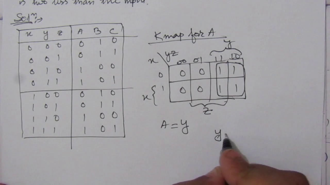
This project is individual assignment no groups is allowed operation 1. Each combination of input variables will affect the output s. System functionality 1 2 note. When the binary input is 4 5 6 or 7 the binary output is one less than the input.
A block diagram of the combinational circuit is shown connected to the decoder display circuit in the following figure. The inputs represent a binary number in the range. When the binary input is 0 1 2 or 3 the binary output is one greater than the input. A combinational circuit can have an n number of inputs and m number of outputs.
Design procedure of combinational circuits.

Https Encrypted Tbn0 Gstatic Com Images Q Tbn 3aand9gcr6o Df7gsnnnzkgehb3dv3xn6a0 Obqerb4g Usqp Cau

Piso Shift Register Shift Register Shift Electronics Circuit

4 Bit Asynchronous Up Down Counter Counter Electronics Circuit Circuit
Combinational Circuits Using Decoder Geeksforgeeks

Pipo Shift Register Shift Register Electronics Circuit Digital
Q 4 5 Design A Combinational Circuit With Three Inputs X Y And Z And Three Outputs A B And C Youtube

Decade Counter Electronics Circuit Counter Circuit

High Voltage Low Current Power Supply 2000vdc From 15vdc High Voltage Power Supply Circuit Ups Power Supply

Lm339 Datasheet Quad Comparator How To Use Eleccircuit Com Quad Circuit Connection
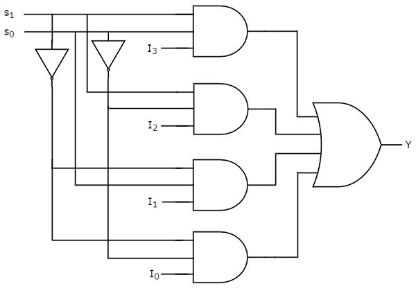
Digital Circuits Multiplexers Tutorialspoint
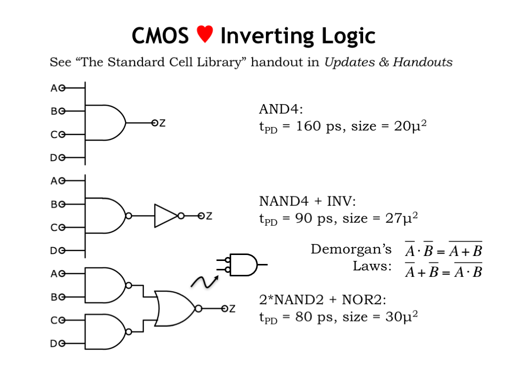
L04 Combinational Logic

Transimpedance Amplifier This Fast Photodiode Transimpedance Amplifier Is Based On A High Speed Jfet Input Op Amp Opa657 Circuit Simulator Circuitry Circuit

Vhdl Code For Sequence Detector 101 Using Moore State Machine And Vhdl Code For Sequence Detector 101 Using Mealy State Machine Coding Detector States

Gray To Binary Code Converter 4 Bit Coding Binary Converter

Railway Points Sequencer Electronic Schematics Electronic Circuit Projects Electronic Circuit Design
Https Ece Uwaterloo Ca Msachdev Ece223 Assignment4 Solution 3rd Edition Pdf

Binary To Gray Code Converter 3 Bit Coding Converter Binary

Carry Select Adder Vhdl Code Coding Carry On The Selection
Https Encrypted Tbn0 Gstatic Com Images Q Tbn 3aand9gctrp1c1lubgfwn7nhpfb69o1dj4hag8oge3agctusex3kh14rlx Usqp Cau

A Transistor Based Computer Circuit Electronics Circuit Transistors Circuit
Vhdl Code For Flipflop D Jk Sr T Coding Binary Code Seniors

Isolated Digital Output Module Ladder Logic Digital Plc Programming

4 Preamplifier Circuits Using Transistors Eleccircuit Com Transistors Electronic Circuit Projects Circuit
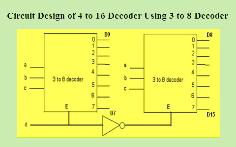
How To Design A 4 To 16 Decoder Using 3 To 8 Decoder

Multiplexer Working Wireless Headphones Workouts Ohms Law Arduino

High Voltage Dc Generator Circuit Schematic High Voltage Circuit Electronics Circuit

A Brief Tutorial On Microstrip Antennas Part 4 Antennas Tutorial Math Software

Full Adder Ladder Logic Siemens Math

7400 Quad Two Input Nand Gate Pin Diagram In 2020 Nand Gate Quad Gate

Pin By Electronicsidlv Wordpress Com On Electrical Electronic Engineering Electronics Basics Electricity

Pin On Amplificador
Construction Of Combinational Circuits Geeksforgeeks
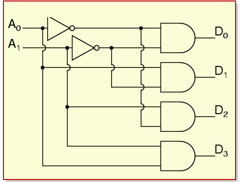
How To Design Of 2 To 4 Line Decoder Circuit Truth Table And Applications

Non Inverting Operational Amplifier Amplifier Electronics Components Arduino

Pin On Sanoop Pcb

Pin On Raspberry Pi

Simple Code Lock Circuit Simple Code Circuit Diagram Circuit

Four Level Audio Power Indicator Red Page184 Power Audio Levels

Waveforms For Low Frequency Pulse At Modulator And Demodulator Circuits Modulators Pic Microcontroller Circuit Diagram

Logic Gate Symbols Chart New Website You Need This Www 10khits Com Electronic Engineering Electronics Basics Electricity

Schmitt Trigger Using 741 Opamp With Proteus Elex Focus Schmitt Trigger Trigger Electronics Projects Diy

If You Are Looking For A Compact Transformerless Ferrite Core Inverter Circuit With Maximum Featur Circuit Diagram Circuit Projects Electronic Circuit Projects

