Cvt Stabilizer Circuit Diagram
Cvt Constant Voltage Transformer Working Circuit Diagram Application

Automatic Voltage Stabilizer Circuit Diagram Circuit Diagram Circuit Diagram

Automatic Voltage Stabilizer Circuit Diagram Circuit Diagram Circuit Pic Microcontroller

Manual Voltage Stabilizer Circuit

Voltage Stabilizer Circuit Diagram Circuit Diagram Circuit Diagram

Electrical Circuit Diagram Of Voltage Stabilizer Electrical Circuit Diagram Circuit Diagram Diagram
It has no moving parts.
Cvt stabilizer circuit diagram. The presets p1 to p7 can be modified as per the needed tripping points which is able to correspond to the output ssr switching and the successive transformer tap. This is required because there is no internal crystal present in pic 16f873a. The cvt has a magnetic circuit which becomes a very low impedance when fed with high voltage. The voltage regulation possible in a cvt also is good.
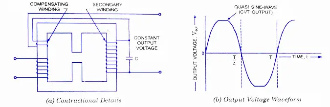
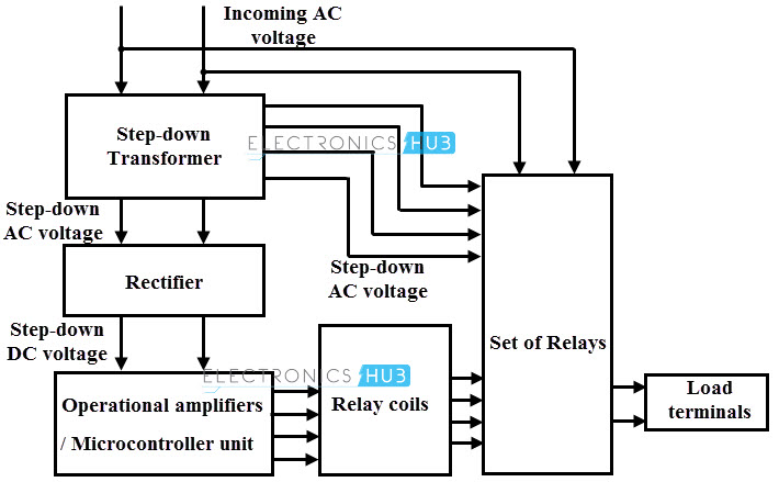
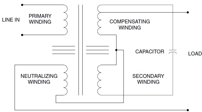
The suggested circuit of a basic 5 kva to 10 kva automatic voltage stabilizer circuit is simple to recognize. A practical circuit of a cvt power supply is given in figure. If you use 12 0 12 transformer then use 24v relay. A special transformer with resonant tank circuit formed by resonant winding and capacitor keeps output voltage constant.
Rating of 50 150 250 350 500 750 1000 2000 va. Like a regular transformer the cvt has a primary and a secondary. Use 500ma to 1 a transformer. Automatic voltage stabilizer circuit diagram 2.
The input voltage ranges 170 to 260 v and output regulation is 230 2 at no load to full load. Here is another simple circuit of autocut for manual stabilizer. Automatic voltage stabilizer circuit diagram voltage stabilizer circuit operation. Due to resonant tank circuit formed by capacitor it is exc.
You can also check this circuit by connecting with 0 12 transformer with 12v relay. The primary is on the side of a magnetic shunt ad the secondary is on the opposite side with a tuned coil circuit. If the unit is correctly installed with a protecting fuse or circuit breaker then the cvt will blow the fuse breaker before damaging energy gets to the electronic equipment being protected. For the microcontroller circuit we use an external crystal of 4 mhz.
Typical schematic diagram of a cvt the main applications of cvt in high voltage networks above 36 kv are given below. A cvt consists of a high voltage resonant winding and a capacitor that produces a regulated output voltage for any type of input varying current. In this circuit there are small changing from the first circuit. Tap voltage approximately 5 12 kv depending on the type is taken from the lowest capacitor section and fed to an electromagnetic circuit in the cast aluminum base box.
Voltage stabilizer repairक य आपक voltage stabilizer भ high voltage द त ह त य video ज र र द ख duration.

Pin On High Voltage Autocut Circuit For Stabilizer

Automatic Voltage Stabilizer Circuit Engineering Projects In 2020 Circuit Circuit Diagram Electronics Circuit

5 Kva To 10 Kva Automatic Voltage Stabilizer 220 Volts 120 Volts Homemade Circuit Projects In 2020 Circuit Bike Repair Circuit Diagram

Pin On Circuit

Mercury Outboard Wiring Diagrams Mastertech Marin Wiring Diagram Mercury Outboard Outboard Starter Motor

Ev 0119 Stabilizer Of Continuous Adjustment Powersupplycircuit Circuit Download Diagram

A 2 Z Stabilizer Diagram Autocut Voltage Stabilizer Circuit Diagram Youtube

H Bridge Mains Voltage Stabilizer Circuit 100v To 220v Electronic Circuit Projects Electronics Circuit Solar Inverter

Wk 2260 15 Volt Stabilizer Circuit Download Diagram

Servo Voltage Stabilizer Manufacturer In Delhi Call 9818596585 Save Energy Electricity Bill High Voltage

90v 280v Automatic Stabilizer Control Board 500va 5kva Amazon In Electronics

Rr 0401 Stabilizer Circuit 220v Stabilizer Circuit 220v Manufacturers In Wiring Diagram

Know What Features Of Automatic Voltage Stabilizer Electrical Problems Manufacturing Repair And Maintenance

Technical Article By Mr

Relay Alingnement Automatic Stabilizer 90v To 280v Yt 27 Youtube
Voltage Stabilizer Working And Its Importance

Capacitor Voltage Transformer Wikipedia
Circuit For Automatic Voltage Stabilizer 5kva To 10 Kva Skill Development Youtube
Search Q 5 Relay Stabilizer Circuit Diagram Tbm Isch

Servo Controlled Voltage Stablizer Single Phase Third Phase Electronics Basics Stability Basic

Anazor Zener Diode As A Voltage Stabilizer Diode Stability Power

What Is A Constant Voltage Transformer An Introduction To The Perfect Sine Wave

Simple 12v 5a Power Supply Regulator Circuit Diagram Electronic Circuit Diagrams Schematics Electrical Circuit Diagram Circuit Diagram Circuit

0 5kva 90v To 300v Manual Stabilizer Wiring Diagram With Data Youtube

Pin On Procarmanuals Com

Ferroresonant Transformer Voltage Disturbance
Antique Radio Forums View Topic Found An Isolation Transformer

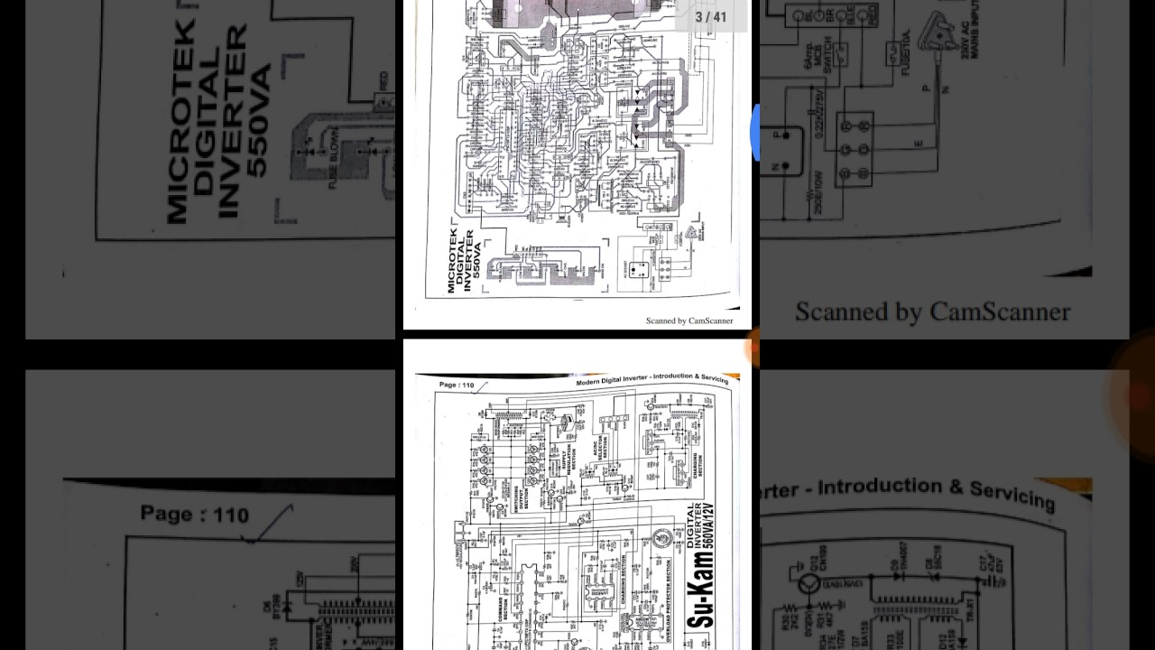
Circuit Diagram Of Inverter Stabilizer N More Youtube

Pdf Design Construction Of A 220v Voltage Stabilizer

Capacitor Voltage Transformer In Hindi Cvt Concept Youtube

Diy Voltage Stabilizer For Ac Utility Electronic Engineering Diy Electronic Cards

10 Kva Voltage Stabilizer Steplezar With Transformer Data 90 V To 290v Youtube
Voltage Regulators Circuits Types Working Principle Design Applications

Cvt Constant Voltage Transformer Principle Voltage Transformer Manufacturer From Indore

Medium Voltage Switchgear 2 Selection Of Switching Devices Power Engineering Installation Locker Storage

Best Stabilizer For Ac And Fridge Youtube

Capacitor Voltage Transformer Cvt Concept Youtube


Constant Voltage Transformers Or Avs Which Is Best Ee Times

Microtek 1 5 Ton Ac Stabilizer Microtek Em4150 Ac Stabilizer Unboxing Review Thenaviin Youtube

Servo Stabilizers Servo Stabilizer Manufacturer From Coimbatore

